 ar
ar bg
bg hr
hr cs
cs da
da nl
nl fi
fi fr
fr de
de el
el hi
hi it
it ko
ko no
no pl
pl pt
pt ro
ro ru
ru es
es sv
sv tl
tl iw
iw id
id lv
lv lt
lt sr
sr sk
sk sl
sl uk
uk vi
vi et
et hu
hu th
th tr
tr fa
fa ms
ms hy
hy ka
ka ur
ur bn
bn mn
mn ta
ta kk
kk uz
uz ku
ku
load cell wiring diagram
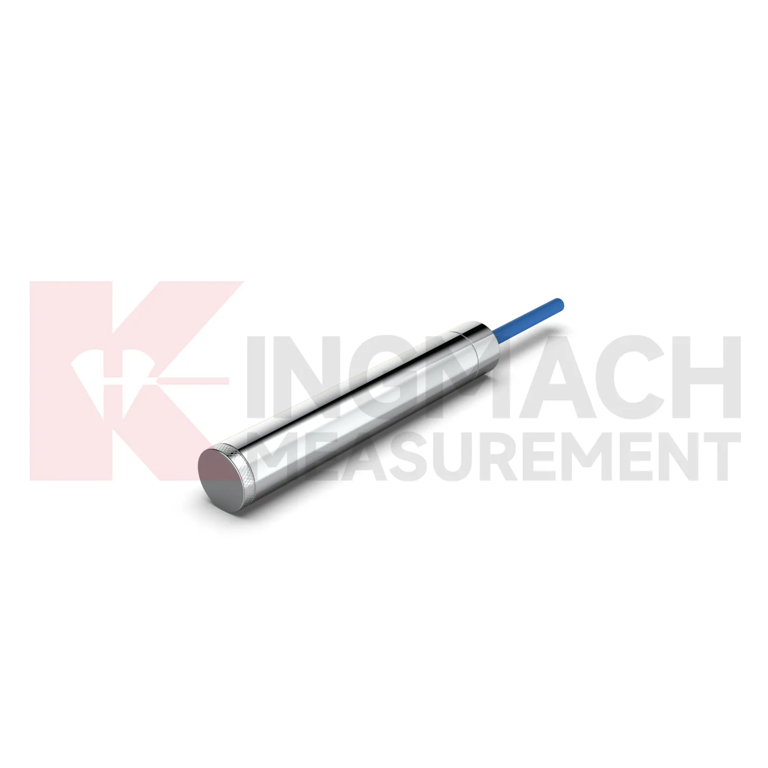
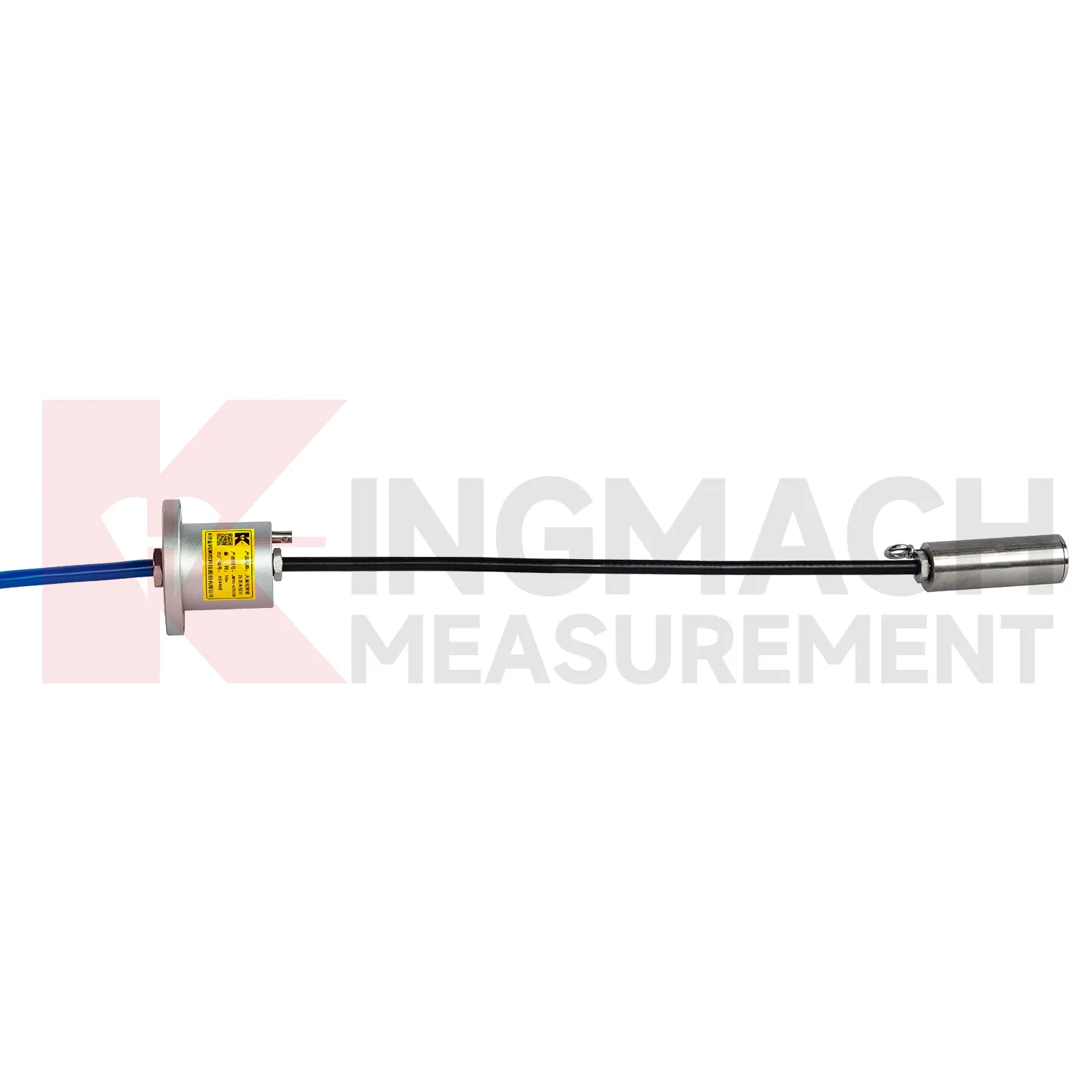
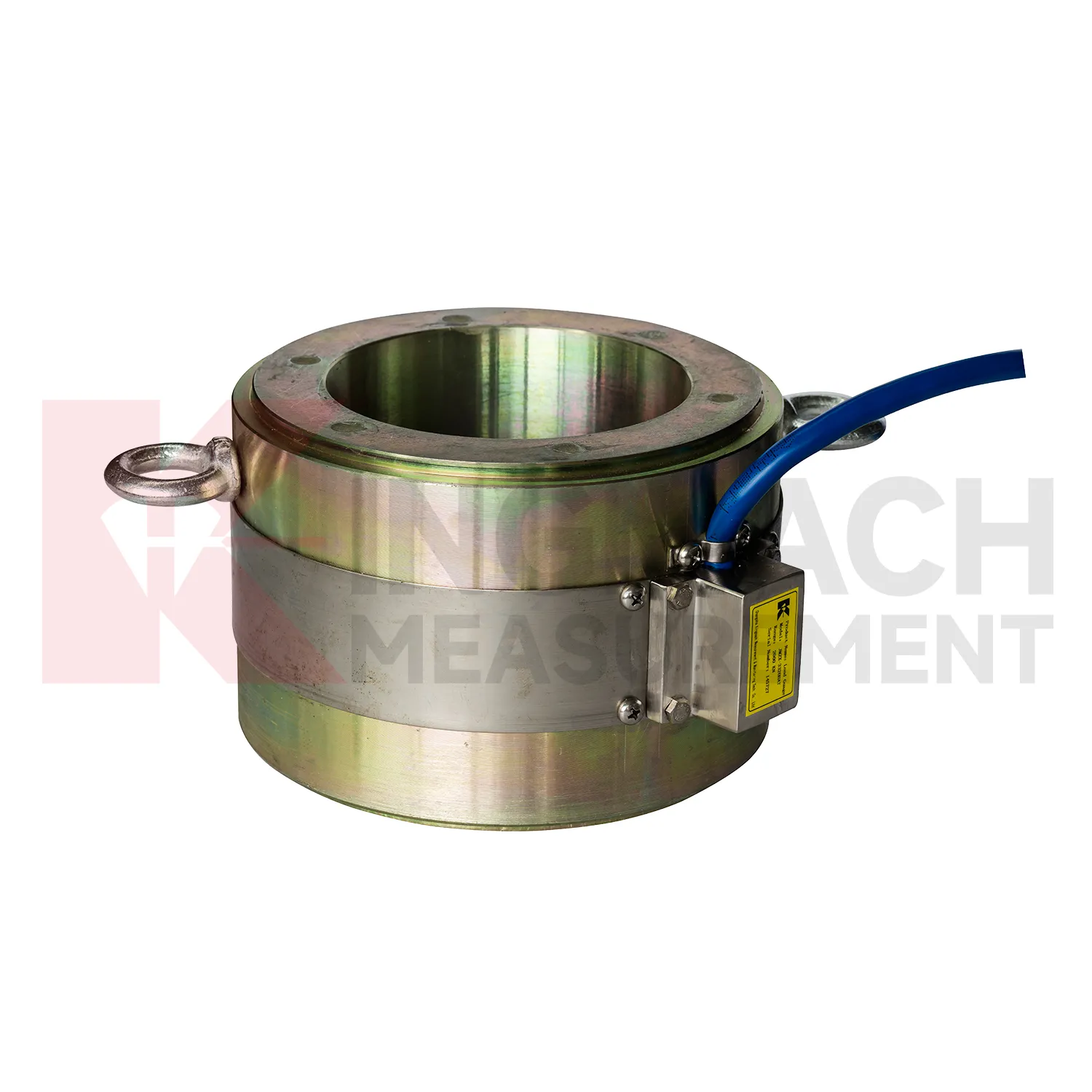
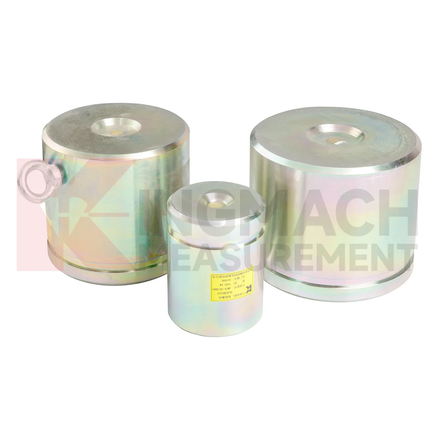
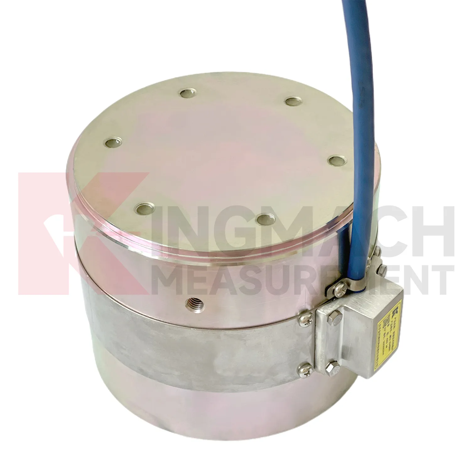
Kingmach load cell wiring diagram product information is especially helpful during early engineering review because it gives model families rather than one generic device. The JMZX-3XXXHAT hollow load cell is tied to annular multi-string construction, elastic steel, ultra-high-strength vibrating wires, anchor welding, temperature correction, and 500 kN to 8000 kN ranges. The JMZX-35XXHAT solid load cell is tied to compression monitoring, 1000 kN to 10000 kN ranges, 0.1 kN resolution, and 0.5%FS precision. The JMZX-38XXHAT axial force meter is tied to steel support measurement, 200 kN to 3000 kN ranges, and 1 MPa waterproof performance. Those distinctions guide model selection before purchase. For a bridge, the force path may require hollow or solid construction. For a tunnel support, direct axial force display may be more practical. For soil pressure, MPa range and buried durability matter more than kN capacity. Matching the type to the load path prevents expensive changes after delivery. The product pages also show that standard models and customized versions may exist side by side. That is important because site geometry, force range, and available clearance may require confirmation before the load point can be ordered with confidence. It also gives the contractor clearer limits for installation geometry, cable routing, waterproof protection, and calibration review before the work reaches the field.
Application of load cell wiring diagram
In building structural health monitoring, load cell wiring diagram can be used around transfer structures, temporary supports, column load checks, foundation testing, and heavy equipment installation areas. The monitoring need is often construction stage control rather than a permanent visible defect. Loads may shift when floors are cast, jacks are released, shoring is removed, or new equipment is placed. Kingmach solid load cells offer 1000 kN to 10000 kN ranges, 0.1 kN resolution, and 0.5%FS precision, with a -30°C to 80°C working temperature range. Axial force meters add direct kN display for steel support points and 0.5%FS accuracy. These parameters help site teams check whether the support path is behaving as planned. The reading should be reviewed together with settlement, tilt, crack gauges, and construction sequence notes. For long term building owners, retaining the original model, calibration coefficient, zero value, and first stable reading makes later inspection far easier when occupancy, equipment load, or renovation changes the load pattern. In buildings, temporary works often disappear after the next construction stage, so the early record should be complete. Photographs of the installed point, bearing plates, cable path, and readout channel can prevent confusion during later structural review.
The future of load cell wiring diagram
For bridge and cable supported structures, future load cell wiring diagram work will likely combine high capacity sensing with digital inspection records. Hollow load cells with 500 kN to 8000 kN ranges and long service design can provide long term anchor or cable force data, while acquisition systems can bring those readings into owner platforms. The technical shift is toward trend based assessment: a cable force value is checked against temperature, traffic, wind, maintenance events, and nearby deformation. Wireless transmission may reduce site visits where access is difficult, although high risk points will still need protected cables, stable power, and field verification. As bridge monitoring requirements become more specific about traceability and response workflow, sensors with stored calibration data and temperature correction will be easier to manage. The most useful future system will not simply send alarms. It will show when the change began, which sensor recorded it, what else changed nearby, and whether the reading matches known structural behavior.
Care & Maintenance of load cell wiring diagram
For load cell wiring diagram used in pile load testing, care begins before the first load step. Confirm that the selected solid load cell range, often between 1000 kN and 10000 kN on Kingmach listed models, exceeds the planned test load with proper margin. Check the 0.1 kN resolution, 0.5%FS precision, calibration certificate, bearing plate flatness, and centering arrangement. During the test, protect the cable from jack movement and keep the readout position safe from vibration and water. Record zero value, temperature, load stage, hold time, unloading stage, and any pause or adjustment. After the test, inspect the sensor for dents, side load marks, connector damage, and cable jacket cuts. Store the calibration coefficient with the test report, not only with the instrument box. If later readings appear inconsistent, compare them with jack pressure, settlement data, and loading procedure before blaming the sensor. Store the report with the test file.
Kingmachload cell wiring diagram
load cell wiring diagram supports decisions that are too important to leave to visual inspection alone. A bridge anchor plate may look unchanged while force redistributes between strands. A deep excavation support may still be straight while axial load rises. A pile test may appear steady while the loading system introduces eccentric force. Kingmach's load monitoring range gives engineers several instrument formats for these different questions, including hollow, solid, axial force, and pressure related products. The field value depends on repeatability. A reading taken today must be comparable with the first stable reading, the next load stage, and the record after temperature changes. That is why calibration coefficients, zero values, cable labels, installation photos, and compatible readouts matter. When all of those details are controlled, force monitoring becomes a practical inspection record rather than a one-time test result. That discipline turns a single load point into evidence that can be reviewed months later.
FAQ
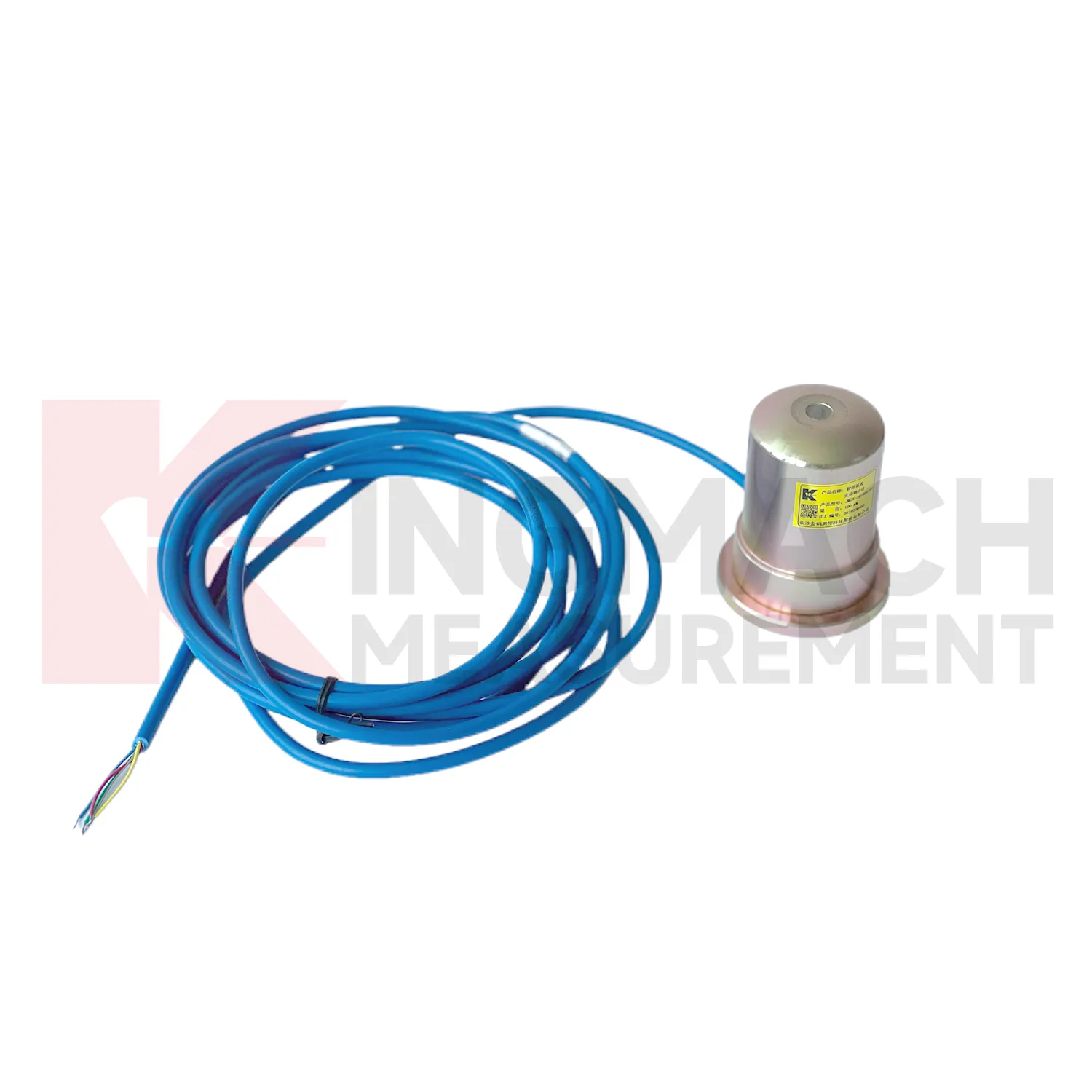
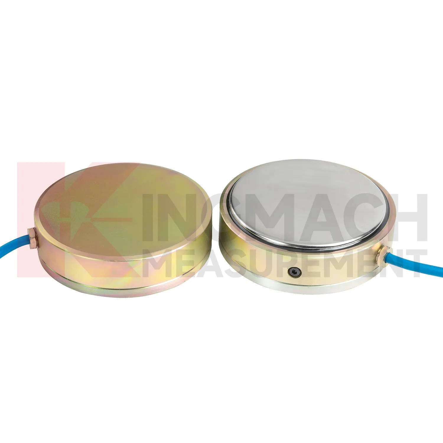
Q: Can load cell wiring diagram be used for soil pressure or retaining wall pressure? A: Yes, pressure related models such as earth pressure cells are used where the measured value is contact pressure rather than direct member force. Q: What ranges are listed for Kingmach earth pressure cells? A: The JMZX-50XXAT/ATM family lists 0.3 MPa, 0.6 MPa, 1 MPa, 2 MPa, 4 MPa, 6 MPa, and 8 MPa ranges. Q: What accuracy and resolution are listed? A: The product file gives 0.001 MPa pressure resolution, 0.5%FS pressure accuracy, and ±0.5°C temperature accuracy. Q: Where are these readings useful? A: Foundation pits, dams, slopes, retaining walls, embankments, tunnels, and buried structures. Q: What maintenance issue is most common? A: Cable damage, water entry, channel confusion, and poor installation records cause many field doubts.
Reviews
Andrew Lee
The visualization software is intuitive and powerful. It helps us analyze monitoring data efficiently.
James Thompson
The tiltmeters and accelerometers are very sensitive and provide precise data. Perfect for our structural health monitoring system.
Latest Inquiries
To protect the privacy of our buyers, only public service email domains like Gmail, Yahoo, and MSN will be displayed. Additionally, only a limited portion of the inquiry content will be shown.
Emma***@gmail.comCanada
Dear Sir/Madam, we are interested in displacement transducers and settlement sensors for a geotechni...
Amelia***@gmail.comSingapore
Hello, I am looking for visualization software for monitoring system data analysis. Please let me kn...